JS1000 Concrete Batching Plant Technical Specifications: Complete Power Configuration and Transformer Selection Guide
Sep 28,2025
As a representative of medium-sized concrete production equipment, the technical parameter configuration of the JS1000 concrete mixing plantdirectly impacts equipment performance, production efficiency, and operational costs. Reasonable power configuration and transformerselection not only ensure stable operation but also significantly reduce energy consumption and improve investment return. This article provides an in-depth analysis of the technical parameters of the JS1000 concrete mixer ,along with professional selection suggestions and configuration solutions.

I. Detailed Core Parameters of JS1000 Mixing Plant
1.1 Basic Technical Parameters
Production Capacity Indicators:
- Theoretical Productivity: 50-60 m³/h
- Discharge Capacity: 1000 L/batch
- Feeding Capacity: 1600 L
- Work Cycle Time: 72 s
- Annual Average Productivity: 45-50 m³/h
Structural Parameters:
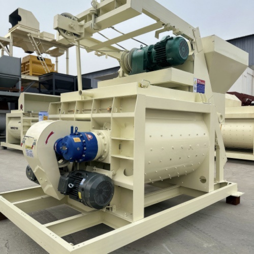
- Mixer Host Model: JS1000 Dual Horizontal Shaft Forced Type
- Hopper Lifting Speed: 18-20 m/min
- Discharge Height: 3.8-4.2 m
- Total Plant Footprint: Length × Width = 25 × 20 m (Basic Model)
II. Detailed Power Configuration Analysis
2.1 Total Power Composition
The total power of the JS1000 mixing plant typically ranges between 90-110 kW, distributed as follows:
Power Configuration of Main Electrical Equipment:
1. Mixer Host: 2 × 18.5 kW = 37 kW
- Drive Type: Dual Motor Drive
- Starting Method: Star-Delta Reduced Voltage Start
- Protection Level: IP55
2. Hoist Motor: 7.5 kW
- Lifting Speed: 18 m/min
- Safety Factor: 1.5x Overload Protection
3. Water Pump Motor: 3 kW
- Flow Rate: 80 L/min
- Pressure: 0.6 MPa
4. Screw Conveyor: 11 kW × 2 = 22 kW
- Conveying Capacity: 80 t/h
- Conveying Distance: 8-12 m
5. Other Auxiliary Power:
- Pneumatic System: 5.5 kW
- Control System: 3 kW
- Lighting System: 2 kW
2.2 Power Calculation and Selection Suggestions
Simultaneity Factor Considerations:
- Maximum Simultaneous Operating Power: 95 kW
- Recommended Total Power Configuration: 120 kW
- Power Factor: 0.85
- Demand Factor: 0.8
Cable Selection Suggestions:
- Main Cable: 3 × 70 + 1 × 35 mm² Copper Cable
- Control Cable: Shielded Twisted Pair
- Grounding System: Independent Grounding Electrode, Ground Resistance ≤ 4 Ω
III. Transformer Selection Guide
3.1 Transformer Capacity Calculation
Basic Calculation Formula:
Total Apparent Power = Total Active Power / Power Factor
= 120 kW / 0.85 = 141 kVA
Considerations:
- Starting Current Impact: 2.5-3x Rated Current
- Future Expansion Needs: Reserve 20% Margin
- Ambient Temperature Correction: Derating for High-Temperature Environments
Recommended Transformer Capacity:
- Minimum Configuration: 160 kVA
- Recommended Configuration: 200 kVA
- Optimal Configuration: 250 kVA
3.2 Transformer Type Selection
Oil-Immersed Transformer Features:
- Capacity Range: 30-2500 kVA
- Advantages: Low Cost, Simple Maintenance
- Disadvantages: Requires Oil Pit Protection
Dry-Type Transformer Features:
- Capacity Range: 30-2500 kVA
- Advantages: Good Fire Resistance, Easy Installation
- Disadvantages: Higher Price, Sensitive to Environment
Selection Suggestions:
- General Conditions: Choose S11 Series Oil-Immersed Transformers
- High Environmental Requirements: Choose SCB10 Series Dry-Type Transformers
- Special Environments: Choose Products with Protection Level IP54 or Higher
IV. Electrical Control System Configuration
4.1 Control Cabinet Configuration
Main Components:
- Main Circuit Breaker: 250 A Molded Case Circuit Breaker
- Contactor: LC1 Series AC Contactor
- Thermal Relay: LRD Series Overload Protection
- PLC Controller: Siemens S7-1200 Series
- Human-Machine Interface: 10-inch Color Touchscreen
4.2 Automation Functions
Basic Control Functions:
- Automatic Batching Control
- Measurement Accuracy Compensation
- Fault Self-Diagnosis
- Production Data Recording

V. Energy-Saving Configuration Suggestions
5.1 Motor Energy-Saving Solutions
High-Efficiency Motor Applications:
- Energy Efficiency Level: IE3 or Higher
- Efficiency Improvement: 3-5%
- Investment Payback Period: 1-2 Years
5.2 Power Factor Compensation
Compensation Capacity Calculation:
- Target Power Factor: Above 0.95
- Compensation Capacity: 50 kvar
- Control Method: Automatic Switching
Configuration Solution:
- Compensation Cabinet: GGJ Series
- Capacitors: BSMJ Series
- Reactors: Matched Reactance Rate 7%
VI. Installation and Debugging Key Points
6.1 Electrical Installation Requirements
Power Supply Connection:
- Supply Voltage: 380 V ± 5%
- Frequency: 50 Hz ± 0.5 Hz
- Voltage Fluctuation: ≤ ±5%
Grounding System:
- System Grounding: TN-S System
- Ground Resistance: ≤ 4 Ω
- Lightning Protection: Secondary Lightning Protection
6.2 Debugging and Testing Items
Electrical Testing:
- Insulation Resistance Test: ≥ 1 MΩ
- Ground Resistance Test: ≤ 4 Ω
- Voltage Balance: ≤ 2%
- Protection Device Test: Reliable Operation
VII. Operation and Maintenance Management
7.1 Daily Inspection Items
Electrical System Inspection:
- Cable Connection Temperature
- Circuit Breaker Status
- Contactor Contacts
- Protection Device Settings
Mechanical System Inspection:
- Motor Operating Sound
- Bearing Temperature
- Belt Tension
- Lubrication System Working Status
7.2 Regular Maintenance Plan
Monthly Maintenance:
- Clean Electrical Cabinet Dust
- Check Cable Insulation
- Test Protection Functions
- Record Operating Data
Annual Maintenance:
- Comprehensive Electrical Connection Check
- Replace Worn Components
- Calibrate Measuring Instruments
- System Performance Test
VIII. Common Issues and Solutions
8.1 Insufficient Power Handling
Symptoms:
- Difficulty Starting Motors
- Excessive Voltage Drop During Operation
- Frequent Tripping of Protection Devices
Solutions:
- Check Power Supply Capacity
- Optimize Startup Sequence
- Increase Reactive Power Compensation
- Consider Transformer Capacity Expansion
8.2 Power Quality Optimization
Common Issues:
- Excessive Voltage Fluctuation
- Excessive Harmonic Content
- Low Power Factor
Improvement Measures:
- Install Voltage Stabilizers
- Install Filtering Equipment
- Optimize Compensation System
- Improve Grounding Quality
Conclusion: Scientific Configuration Ensures Efficient Operation
The parameter configuration and power selection for the JS1000 concrete mixing plant is a systematic project that requires comprehensive consideration of equipment performance, power supply, environmental conditions, and other factors. We recommend:
1. Professional Design: Engage professional electrical engineers for system design.
2. Quality Priority: Choose high-quality electrical equipment and components.
3. Reasonable Redundancy: Reserve appropriate power margin.
4. Regular Maintenance: Establish a sound maintenance system.
Through scientific configuration and standardized management, your JS1000 mixing plant will operate stably and efficiently, creating greater economic benefits.
If you need detailed technical solutions or personalized configuration suggestions, please contact Tongxin Machinery's technical team and we will provide professional technical support and services.
![[Recommended] JS750 concrete mixer, factory direct sale! Save time, effort, and money!](/uploadfile/202509/8466736764d811a.jpg)